Dead band
Dead band is a situation where there is no output for any input; the control valve system is essentially dead. Dead band mainly occurs when the valves need to change the direction, either intentionally or accidentally, from sources.
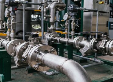
Source: UNSPLASH
A rise in loop deadtime is the Dead band divided by the change of controller output rate. The peak and integrated errors can be increased in load disturbance due to an increase in dead time. In case of dual or more integrators in the system due to integral action in the valve positioner, uneven speed in controllers or processor limitations in cycles will develop.
Symptom & Indication
When the controller signals fail to detect or trigger any valve activity, these are the signs of a Dead band. In the case of a Dead band, the control valve reacts to backlash between the controller output and valve position.
Indicators of high Dead band
· Increase in errors from load disturbance
· Rise in system dead time
· Frequent fluctuating control loop
· Uneven control
How to Fix
As the controller output changes direction, the dead band needs to be stretched across before the valve physically starts moving. In some cases, a Dead band is useful, but in most applications, the effects of a Dead band are disastrous.
For the control valve, the ideal solution is to get rid of the Dead band extensively. When you are stuck with the Dead band principal in a big valve source, an increase in PID (proportional integral derivative) gain can decrease the Integrated Absolute Error by raising the rate of change of PID, thus decreasing the decrease deadtime due to Dead band.
The practical issue faced is Dead band sometimes varies with valve position, operating conditions, and time of positioner tuning; the impact of output upon a change in direction removes the deadtime and loss of motion from the backlash.
How to Avoid
Although mechanical backlashes cause Dead band to occur due to loosening or mechanical linkage, excessive friction in the valve, a defective positioner, or a reduction in the size of the actuator can also cause Dead band to arrive.
Having isolation or on-off valve gives a great advantage when used in series along with the throttle valve. The throttle valve is placed at a more accessible position for better maintenance for some upstream and downstream runs, which require a minimum but can offer a more consistent flow relationship between the valve position.
The increased deadtime of the Dead band is not visible in open-loop step tests, but the procedure of reversing the direction of step change is reduced.
A basic algorithm can be configured to upfill the change in PID output with a slightly adjusting less amount than the Dead band where the output changes direction with a greater noise band seen in the PID output.
Stiction
Another common issue found in the control valve loop is Stiction, a combination of words stick and friction. This term is a condition that holds the valve in a particular condition and sticks it there, not allowing it to move like a Dead band. In a stiction condition, the movement of the valve needs additional force, which can also cause the valve to overshoot its position and its process setpoint like the Dead band, leading the valve to get stuck in a new or wrong position.
Stiction is often found in control loops operating in pre-set mode as a continuous cycling pattern of controller output and a square wave pattern of process variables producing process disturbance and valve tears.
Symptom & Indication
If the CO is noticed to move more than 0.5% in each cycle, then there is a stiction problem
· There may be sticky valve internals
· Undersized actuators
· Media Viscosity
· Tight Shutoff
· The control valve will never meet the desired set point in stiction
· The valve keeps on sticking to a new position
· The controller output reverses the direction, and the whole process functions in opposite directions
· A loop cycle is caused due to stiction; the control valve output movement will be like a saw-tooth wave, while the process may look like a square wave or irregular sine wave.
How to Fix
To fix the problems related to Stiction in the valve, it has to be assured that the valve actuator and positioner are sized properly to adjust the force required to move the valve.
Identifying the air pressure of the valve meets the recommended air supply by the control valve manufacturer. Having a check of the torque on the valve packing gland.
It is also recommended to have a visual inspection of the valve’s internals for signs of scaling, scarring, or wear and tear, having to replace the valve as needed. Using viscous or sticky process fluid enhances the problem of stiction, locating the valve, checking for its orientation, and evaluating whether the valve is less exposed to stickiness as high-performance butterfly valves can be a replacement option.
How to Avoid
The stiction or binding problem in valves is caused due to a few things that need to be fixed to avoid these frequent sticking of valves.
The main cause of stiction is the packing either tight or damaged; this packing needs to be replaced with a new set and tighten the flange of packing until hand tight and just a single turn with the spanner.
Inspect regularly if it is straight; any marks or rough surfaces by running your hand over the entire surface will be a good examination process. If there are areas suspected of uneven changes in the valve, clean it and smooth it with fine grinding paste and install it thoroughly.
Positioner overshoot
The additional problem in these recent years found to be more common is position overshoot. These positioners are fast feedback controllers measuring the valve stem positioners that manipulate the valve actuator to reach the desired position of the valve. Most of the valve positioners are capable of tuning; they have tuned too aggressively for their particular controlling valves causing the valve to overshoot its position with a change in controller output.

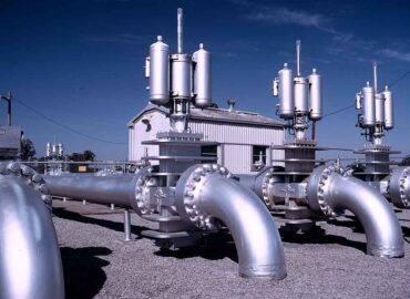
Source: UNSPLASH
In some cases, the positioner is simply defective in a way that causes it to overshoot. If the process controller is also aggressively tuned, it combines with the valve positioner to cause positioner overshoot leading to severe fluctuation in the control loop.
Symptom & Indication
The control valve positioners may have been stroked several times throughout the usage; there may be screw repositions and weakened components such as springs and mechanical linkage. These valve positioners undergo repeated seating of the valve and liquid or gas passing through it.
Usually, valve positioners allow tighter control over the process, but a damaged positioner will overshoot without maintaining the accurate speed and not meeting the valve’s setpoint. Additionally, these positioners will show reduced friction and affect the smooth performance; components experience calibration drift causing the valves and positioners to function with obligations prematurely and operate with improper regulations from glasses and liquids.
How to Fix
The integral time in the control valve acts as an error later, and the offset can be removed by setting a low integration period. Adjusting the integral, proportion, and derivative parameters can control the positioner overshooting. Practice increasing the integral time value in small increments until the fluctuation is noticed to eliminate the offset.
The derivative time works as decelerate in controlling the loop in some of the applications, while in other control valve applications, a slight overshoot is tolerated. In some cases, the derivative control can reduce the overshoots. Still, it can result in a lack of desired responsiveness so that the derivative time can be utilized as per the response to changes are optimized.
How to Avoid
Working on only one adjustment at a time is recommended; acting on all the controls may cause disorientation, and valve setting may move the positioner.
Proportional gain controls the speed of the process racing towards the setpoint; setting high gain can reach your setpoint quickly but will result in a drastic overshoot and fluctuations of the positioner. A low gain may prevent an overshoot but may take longer to achieve the setpoint.
As a safety measure to avoid any overshoot, initially set the integral time, derivative time, and proportional time at zero and then increase the proportional gain value gradually in small portions till the occurrence of oscillation, and then reduce the setting.
Incorrect valve sizing
Furthermore, problems in control valves are the improper sizing or oversized valves. These incorrect-sized valves can make the problems worse, especially in smaller-sized valves. Valves should be in the proper size to obtain the travel flow accurately, depending on the valves’ characteristics, curves, and service conditions.

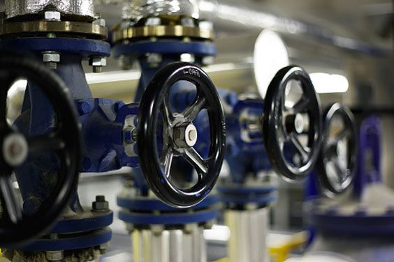
Source: UNSPLASH
An oversized control valve, even a slight change in valve position can affect the flow hugely, and in undersized control valves, there are situations of bottleneck occurring. In some cases, there are larger-sized control valves than the flow rate they need to control, leading to the valve operating at a small opening even at full flow conditions.
Symptom & Indication
Frequent opening and closing of the control valve causing it to be unstable indicates that the valve is oversized. The valve is constantly trying to meet your desired setpoint, but due to its sizing issue, it cannot precisely meet the desired flow of pressure at the setpoint.
Another symptom is water hammering, and it may occur in gas or oil applications when there is a sizing problem in control. This can cause the valve to shut violently, leading to stretch and eventually compromise on the valve stem. Water hammering over time may also stress the coupling block and valve seat to break.
The incorrectly sized valve can also lead to a high stroke count causing the valve to wear down over time much faster than it is supposed to be in normal operating conditions.
How to Fix
Incorrect valve sizing can cause poor control performance due to valve positioning errors, such as stiction and Dead band, which are results of oversized valves. Sizing problems can also be fixed by conducting a few changes in the output by controlling it in manual mode or by managing setpoint changes in auto mode. At least two changes in process in each direction; the larger the change is, the better.
An adequate percentage of the control valve should be optimized when the pressure across the valve decreases as the flow rate increases, to be used in control loops where the process again decreases and flow increases repeatedly.
How to Avoid
It is preferable always to have a minimum opening up to 20% and a maximum of 80% for keeping the safety factor on both ends. The flow characteristic is inaccurate if a set of tuning parameters only works towards one end of the control range and not the other.
A proper-sized full-ball valve, segment-ball control valve, and high-performing butterfly valves are often two sizes smaller than the actual line. Even the smallest changes made in the positioning of the valve can cause a significant change in inflow.
An oversized valve is extremely sensitive to operating conditions, making it difficult or even impossible for the valve to adjust exactly to the required flow.
Nonlinear flow characteristic
Control valves are designed to have a linear flow. Hence, a non-linear flow also leads to tuning problems. So all the above conditions including, Dead band, stiction, improper sizing, and positioner overshoot, can cause non-linearity. The flow characteristic of the control valve is the relationship between flow rate and valve position under normal operating conditions, which is supposed to be linear.
A nonlinear characteristic can provide only optimal controller response at the operating point; this loop could be utterly unstoppable or stagnant as the valve position may move away from its operating point.
Symptom & Indication
Nonlinear flow in the control valve shows signs at the first hint of trouble; this valve will start vibrating and loosen some internal parts with rising problems. There can be seen reverse flow and excessive wear and tear of components. As these valves break down due to nonlinear flow, they create noises, also known as water hammering.
This type of water hammering leads to disturbing the flow and causes disc slamming into the valve’s seat. Thus, causing ruptured pipelines and severe damage. Damage in the flow characteristic also gradually causes sticking and valves’ leakage as they break down.
How to Fix
For solving the nonlinear flow of problems in control valves-
The most important measures for solving control valve issues are ensuring the valves are used properly as directed; each valve must be installed and maintained correctly. Selecting the appropriate valve for its defined application helps keep the concentric butterfly valves functioning properly.
Also, replacing the valves when there are symptoms noticed for ensuring optimum operation and safety—failing to replace the valves after indications of wear and tear may lead to an ultimate system failure.
How to Avoid
As preventive measures to avoid faulty valves and severe damages,
Keep these valves clean as there may be contaminants and debris, leading to blockages and leaks causing valve failure and nonlinear flow; keeping the pipes clean is the easiest and effective way to save from any harm.
Installation of filters and covers can avoid debris from entering the system wherever appropriate. Regular flushing of the liquid systems and pumps also helps to keep the system clean.
Use appropriate lubrication for valves regularly for achieving enhanced performance and smooth operations. Lubricating regularly also extends the life of the valves and the system they are working.